Advanced Optics module
Applications - Scattering Surfaces - Particle Scattering - Quantum Dots- Tandem Solar Cells - Birefringence
OLEDs
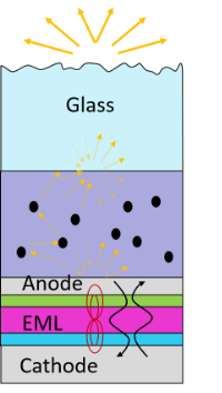
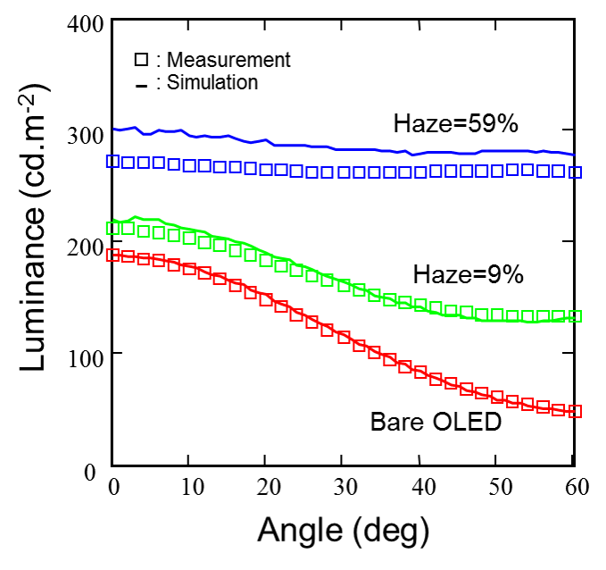
Around 80% of the emitted light in a flat OLED is trapped (and lost) inside the organic and substrate layers. Optical scattering greatly improves the efficiency of OLEDs. The Advanced Optics module has been developed to design scattering layers and optimize the OLED efficiency with these additional features.
Simulation of scattering by structured electrodes (external scattering)
Scattering by nanoparticles in the bulk (internal scattering) by using Mie theory.
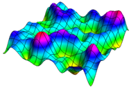
Import rough surface textures from profilometric data or use the synthetic rough surface generator in Setfos
Combine multiple scattering layers within the same device.
Solar Cells
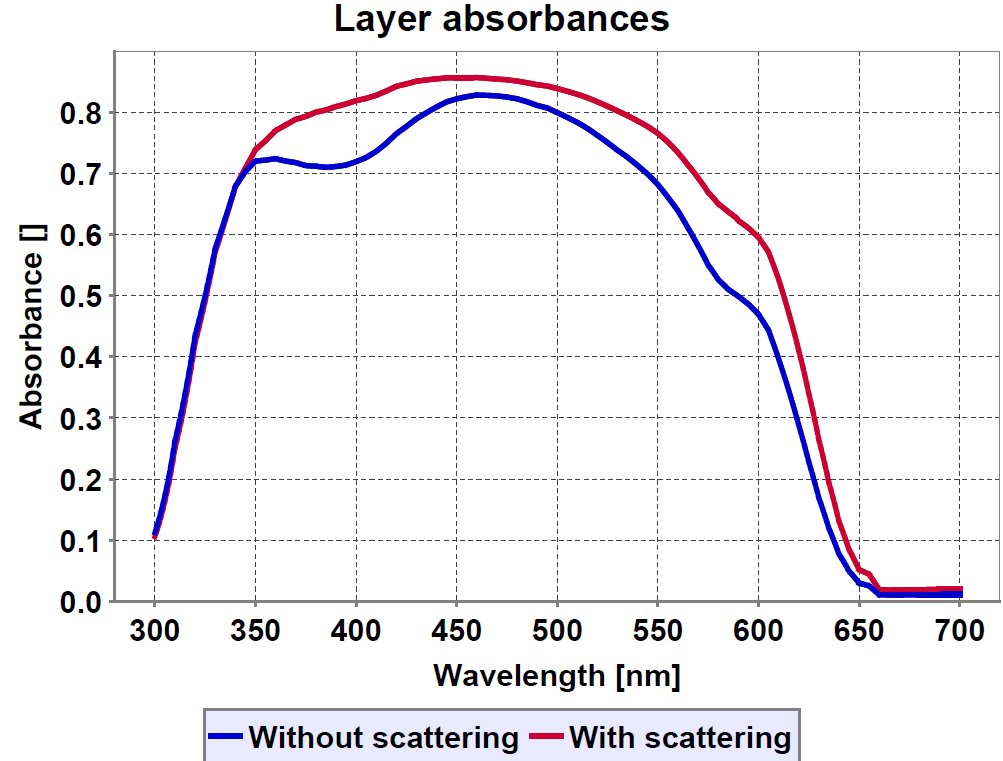
Light management layers are employed to enhance the absorption of thin-film solar cells. The Advanced Optics module enables the fast design of the scattering layer and the thin film stack of organic and perovskite solar cells.
Optimize the scattering layer and the thin-film stack, simultaneously.
Design scattering surfaces and particle dispersions.
Analyze absorption in the active layer and parasitic absorption per wavelength.
Workflow
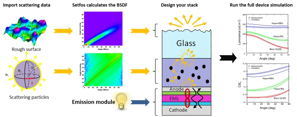
Scattering Surfaces
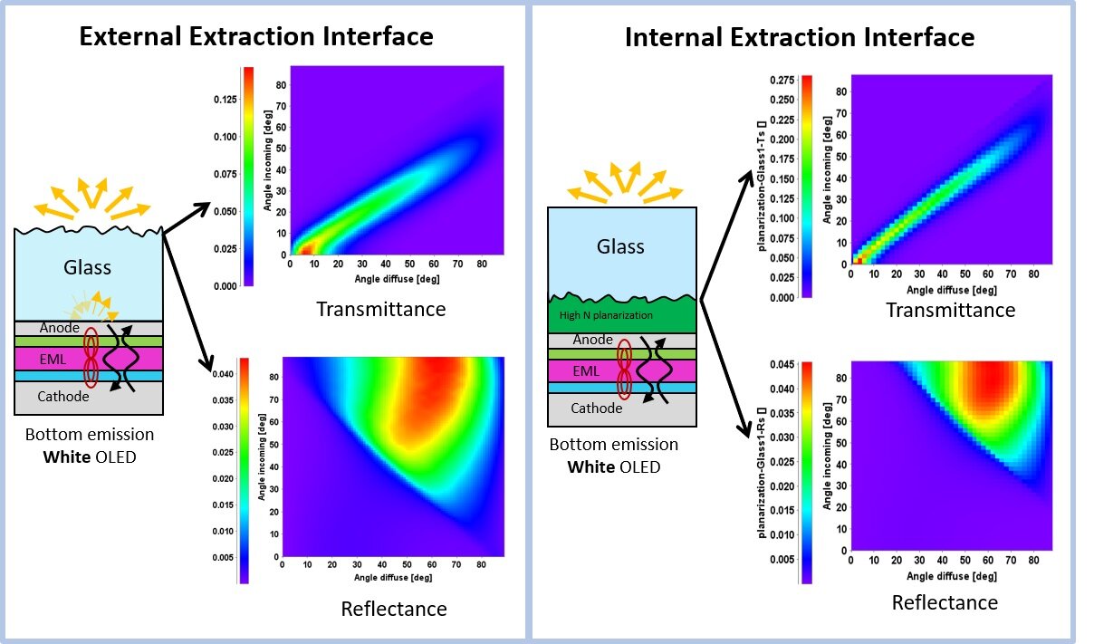
Non-flat layers of micro- or nanosized features scatter light outside the specular directions both in reflection and transmission. This interface scattering can be external, at the air interface, or internal in the layer stack. Setfos can treat the wide variety of structuring methods used throughout industry and academia. It calculates the bidirectional scattering distribution function (BSDF):
Import texture data from profile measurements (AFM).
Employ analytical scatter distribution functions to find the optimal BSDF.
Import experimental BSDF data.
Simulating microlenses and -textures via ray-tracing.
Simulate using geometric (ray) or physical (wave) optics.
BSDF of rough surfaces for both External Extraction Interfaces and Internal Extraction Interfaces
Scattering Particles
Micro or nanoparticles dispersed in a host material form effective scattering layers. Setfos Mie Scattering allows to:
Optimize concentration and refractive index of particle scattering layers.
Simulate the effect of the particle size distribution.
Consider the effect of spherical particles of any size.
Vary the physical parameters of the host material.
Combine stack and outcoupling layer design.
Quantum Dots

Quantum dots are used to expand the color gamut of displays and convert light to lower wavelengths in solar cells. Setfos can simulate the interplay between the nanocrystals and the optical environment:
Simulate mixtures of different types and concentrations of nanocrystals, including self-absorption.
Combine quantum dots with scattering particles. Ray-tracer model for both down-conversion and Mie scattering
Calculate the angular dependence of absorption and emission of thin-film stacks containing a layer of quantum dots.
Interfaces in Tandem Solar Cells
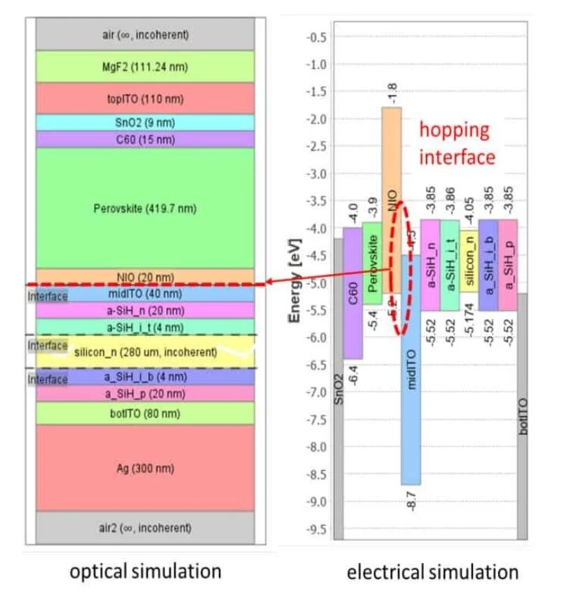
The advantage of perovskite solar cells is that they absorb light better than an indirect-band semiconductor, such as silicon. This is true, especially in the visible part of the spectrum. When a perovskite-based solar cell is coupled with a device made out of crystalline silicon, the combined system can absorb the solar radiation efficiently in both the visible (where the perovskite plays a major role) and the near-infrared.
This structure is commonly called a perovskite-silicon tandem solar cell and can be simulated with Setfos.
Optical simulation of organic and hybrid multifunction and tandem solar cells.
Coupling with the drift-diffusion model for a full optoelectrical simulation.
The explicit consideration of the recombination junction and of mobile ions enables the assessment of electrical losses.
Useful for device design and optimization of tandem solar cells both electrically and optically.
Birefringence
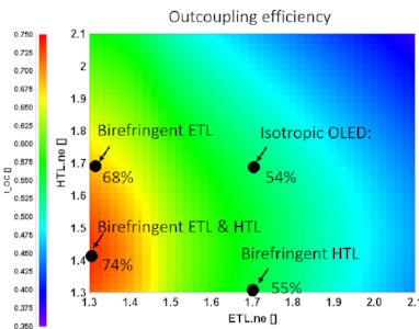
Both small organic molecules and polymers can exhibit birefringence, which influences the characteristics of the device. Setfos calculates the effects of uniaxial anisotropy in a thin film micro-cavity and in the OLED emitting material.
Simulate devices with layers having a refractive index with ordinary and extraordinary components.
Determine the emitter orientation in a birefringent emitting layer.
Download the Setfos Brochure
Additional Modules

EMISSION

Drift-diffusion

Absorption